 |
 |
Features of the Onguard 800 System Fault Module
- Monitors complete 800 panel
- Announces the removal of any module
- Announces any open fuses
- Fault relay output
- DC low and high voltage limit monitoring
- Auxiliary fault input connection
- Audible fault can be silenced
- All field wiring supervised per NFPA
|
|
 |
 |

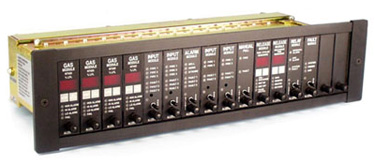
Onguard 800 System Fault Module
The Fault Module is a common system annunciator triggered by any faults in the system. All faults are displayed locally on each module but are also transmitted centrally to the Fault Module, sounding a sonalert. The sonalert can be silenced while determining the source of the fault. A fault will be noted with the system fault LED and de-energize the failsafe fault relay output.
A protection circuit monitors the power supply voltage for under or over voltage inputs. Should the power supply voltage deviate from its required specification, the system fault LED will illuminate and the sonalert will sound, followed by the relay changing state.
An auxiliary normally closed input is provided to monitor any dry contacts. If the contact is open, the auxiliary LED will illuminate and the sonalert will sound followed by the relay changing state.
Approvals
Specifications of the Onguard 800 System Fault Module
| Electrical |
Approved operating voltage: |
20 - 28 VDC redundant power sources |
Operating current: |
31mA quiescent, 40mA maximum |
Dry relay outputs: |
5 amps, 30 VDC resistive
Output relay sealed and contains an inert gas
Relay is form C configuration |
| Mechanical |
Size: |
1.04"W X 3.46"H X 6.4"D |
Weight: |
3.1 ounces |
| Environment |
Ambient operating temperature: |
0°F to 150°F
-17°C to 65°C
90% humidity non-condensing |
RFI interference: |
Meets factory mutual specification as listed in Class #3820 |
Packaging and exposure: |
NEMA 1 |
| Part Number |
Description |
800-1444 |
Fault Module |
800-1186 |
System manual |
Onguard 800 Series Gas and Fire Control Panel Components

|


