|
|
Features of the Onguard
800 Series Gas and Fire Control Panel
- EIA standard 19" width panel
- Integrates gas and fire control in same enclosure
- Designed for special hazard industrial environments
- Conforms to all NFPA standards for signaling and releasing
- Abort module available to hold-delay or restart discharge
- Release module is able to activate a reserve tank if the first tank fails, or fire remains after first tank is released
- Fully automatic operation
- Inhibit to invoke a system test
- 24VDC input can use customer redundant power rail
- Voting capabilities
- Time delay for single spectrum detectors
- Low power CMOS and microcomputer design
- Three year parts and labor warranty
800 System Applications
- Oil refineries
- Chemical plants
- Aircraft hangars
- Nuclear power plants
- Off shore oil platforms
- Co-generation power plants
- Natural gas compressor stations
- Petroleum products pumping stations
|
|
|
|
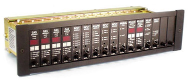
Onguard 800 System Concept
The Allestec 800 series gas and fire control panel is designed to supervise and respond to the result of a gas or fire signal while maintaining simple panel annunciation. This modular hardwired system is primarily suited for the end user who requires a minimum learning curve and simplicity in installation as well as operation. One panel assembly is designed to accommodate small to medium requirements. As many as 32 points of initiating devices can accommodate a panel assembly. Field wiring is completed on a point to point installation between devices and the panel. A remote abort is possible with the optional digital Abort Panel. Completely occupied, the entire panel dimensions are only 3.5" high X 19" wide X 7" deep.
Selectable Modules
Task specific modules perform functions related to their respective input detectors or output appliances. The modules can be selected to accommodate the best possible configuration while allowing room for expansion as necessary. Removal of any module from the slot will induce a system fault.
System Events
All faults are displayed at the lower half of the modules and are bussed to the system Fault Module. The Fault Module can be silenced for any successive faults. All faults will be locally announced at their respective modules and transferred at the Fault Module. All audible appliances can be silenced locally or remotely. An inhibit function is provided to allow system testing of all operations without solenoid activation. The panel cannot be reset until all active alarms have been cleared.
Protection
The system is protected from reverse voltage polarity, power surges, and RFI energy. Under voltage or over voltage from the redundant power source will induce a fault and be displayed on the Fault Module. A cover protector plate spans the length of the rack, containing the wire and associated terminal strips. Flow through ventilation allows cool and silent operation without the need of forced air. The optional locking clear Plexiglas door opens for total access to the front of the panel.
Power
Allestec has designed the panel to accept customer available redundant power supplies. Although the panel is designed and approved for 20 - 28VDC operation, a source voltage as low as 14VDC will operate panel.
Quality and Reliability
High quality components are carefully selected for the manufacturing of the panel. All output relays are sealed and contain an inert gas to prevent contacts from oxidizing. All standard resistors are carbon composition quality. Precision resistors selected are long term stability military type conformal coated RN series. All contact mating surfaces are gold plated to enhance signal conduction and reduce oxidation. Printed circuit boards contain double sided plated through holes. Solder mask is over bare copper to pre-vent wetting action from wave soldering. All modules are cycled with elevated heat in the environmental chamber prior to testing.
Approvals
Specifications of the Onguard 800 Series Gas and Fire Control Panel
| Electrical |
| Approved operating voltage: |
Customer supplied 20 - 28 VDC redundant power sources |
| Absolute lowest operating voltage: |
14 VDC |
| System power requirements: |
Dependent on quantity and type of modules installed |
| Dry relay outputs: |
5 amps, 30 VDC resistive
All output relays sealed and contains an inert gas
Relays customer selective for N.O. or N.C. |
| Environment |
| Ambient operating temperature: |
0°F to 150°F
-17°C to 65°C
90% humidity non-condensing
|
| RFI interference: |
Meets factory mutual specification as listed in Class #3820 |
| Packaging and exposure: |
NEMA 1 |
Onguard 800 Series Gas and Fire Control Panel Components
|